Get in touch with Dreamland Playground Company

Updated August 2026
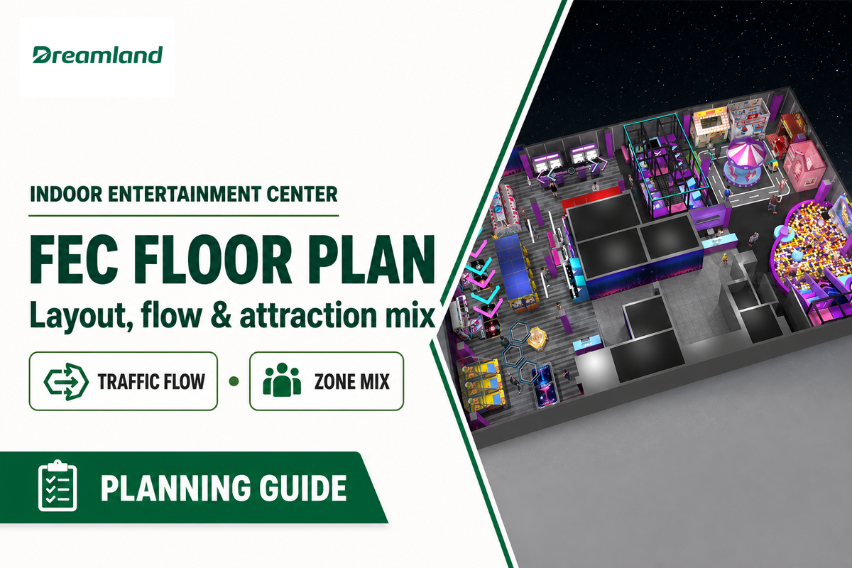
An indoor entertainment center design layout is a concept design model for an entertainment facility that works only when the building shell, guest demand, attraction mix, traffic flow, staffing, accessibility, and approval path are tested as one operating system. This guide shows how to turn those inputs into a floor plan that can be challenged before equipment positions and utilities are frozen.
Indoor entertainment center design layout planning starts with five layers: shell, demand, mix, flow and operations, then validation. Allocate only net usable area, test conflicts under several operating scenarios, and keep operational circulation separate from code-governed accessibility, occupant load, and egress.
Planning brief
- There is no authority-backed universal FEC zone ratio in the reviewed evidence.
- A queue overlay does not replace occupant-load, exit-capacity, or accessible-route review.
- Attraction-level accessibility can extend beyond the path through the venue.
- Every provisional dimension, capacity, and share needs an owner and verification method.
| Item | Working rule |
|---|---|
| Primary output | A testable concept plan plus assumption register |
| Core layers | 5: shell, demand, mix, flow and operations, validation |
| Required scenarios | Ordinary, peak, party turnover, attraction downtime, emergency |
| Ratio status | Project hypothesis, not a universal standard |
| Approval boundary | Authority having jurisdiction and qualified project team |
Treat the FEC Floor Plan as an Operating Model
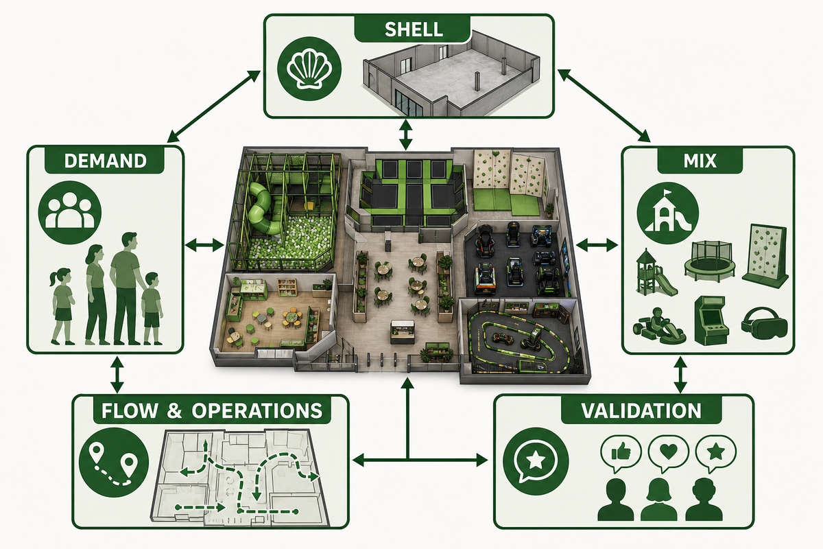
Workable family entertainment center floor plans record how the venue is meant to operate, not just where equipment fits. Under that owner-and-verification rule, each plan connects verified building constraints, guest-demand scenarios, attraction roles, circulation, staffing, support spaces, and approval checks throughout the design process so that one change can be traced through every affected decision before the concept advances.
5-Layer FEC Floor Plan Framework
5-Layer FEC Floor Plan Framework is a sequence for testing shell, demand, mix, operations, and validation as one plan.
| Layer | Question | Evidence to freeze |
|---|---|---|
| 1. Shell | What can the building physically and operationally support? | Measured survey, structure, services, exits, clear heights |
| 2. Demand | Who arrives, when, in what group pattern? | Target audience and operating scenarios |
| 3. Mix | What role does each attraction play? | Capacity, queue, dwell, staffing and utility assumptions |
| 4. Flow & operations | Can guests and staff complete their journeys without conflicts? | Adjacency, service, visibility and queue overlays |
| 5. Validation | Who confirms each safety, access and approval interface? | Owner, source, date, status and change trigger |
Consider a concept team that moves a trampoline park entrance to improve the first view from ticket counters. Moving it may shorten one guest path, yet it can also shift a queue toward seating areas, change staff coverage, alter acoustic exposure, and affect an accessible connection. Decision registers reveal those linked consequences before the drawing becomes visually persuasive but operationally brittle.
Key takeaway
Floor plans are ready to advance only when every red-line assumption has an owner, a verification method, and a defined effect on the other four layers.
Map the Shell and Calculate Net Usable Area
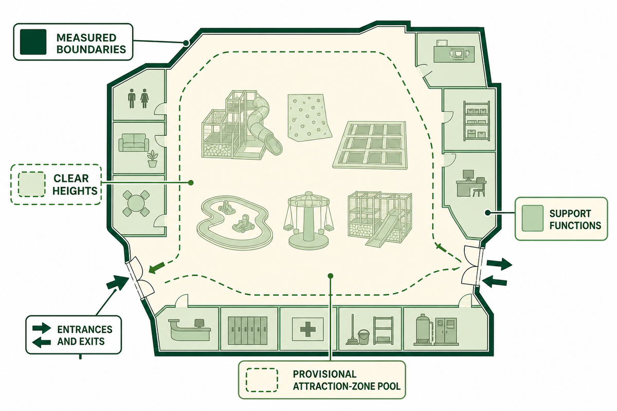
Shell mapping converts a lease plan into a constraint map before attraction areas are assigned. Record measured boundaries, columns, level changes, clear heights, entrances and exits, HVAC, sprinklers, utilities, floor conditions, acoustic interfaces, back-of-house needs, and every item that still depends on landlord, supplier, or authority confirmation.
For an indoor playground or FEC, Playground Professionals quotes Michaella Zahn of Soft Play identifying site-plan accuracy, ceiling height, HVAC, sprinklers, flooring, sightlines, entrances and exits, traffic, seating, controlled access, supervision, and adjacent activities as design inputs. Her list is useful for discovery, but the project survey and qualified consultants must verify the actual conditions.
“Sight lines, entrances and exits and anticipated traffic flow patterns” belong in the play-unit design discussion.
Start with a net-area waterfall: gross measured floor area minus fixed building losses, mandatory support functions, and project reserves equals the available space for attraction zones and their queues. Simple subtraction is not the hard part; deciding which inputs are confirmed is.
Illustrative net-area waterfall
30,000 sq ft gross − 3,000 sq ft fixed shell losses − 5,000 sq ft support and back-of-house − 4,000 sq ft circulation/queue reserve = 18,000 sq ft provisional attraction-zone pool.
These numbers demonstrate the calculation only. Replace every input with measured, approved project data.
One common mistake is drawing a full entertainment mix on the gross square foot figure, then discovering that electrical rooms, food preparation, storage, party staging, ticket counters, accessible routes, or queue envelopes were never deducted. A small indoor entertainment center design layout is especially sensitive to hidden support-space deductions. Run an early play-zone clear-height check, then test the measured inputs in the mall play-area space planner.
Do
- Measure the actual shell
- Tag every unknown
- Reserve support functions first
- Record the source and date
Don’t
- Plan from leasing area alone
- Treat clear height as uniform
- Hide queues inside circulation
- Publish an unverified ratio
Define Demand Scenarios and Build the Attraction Mix
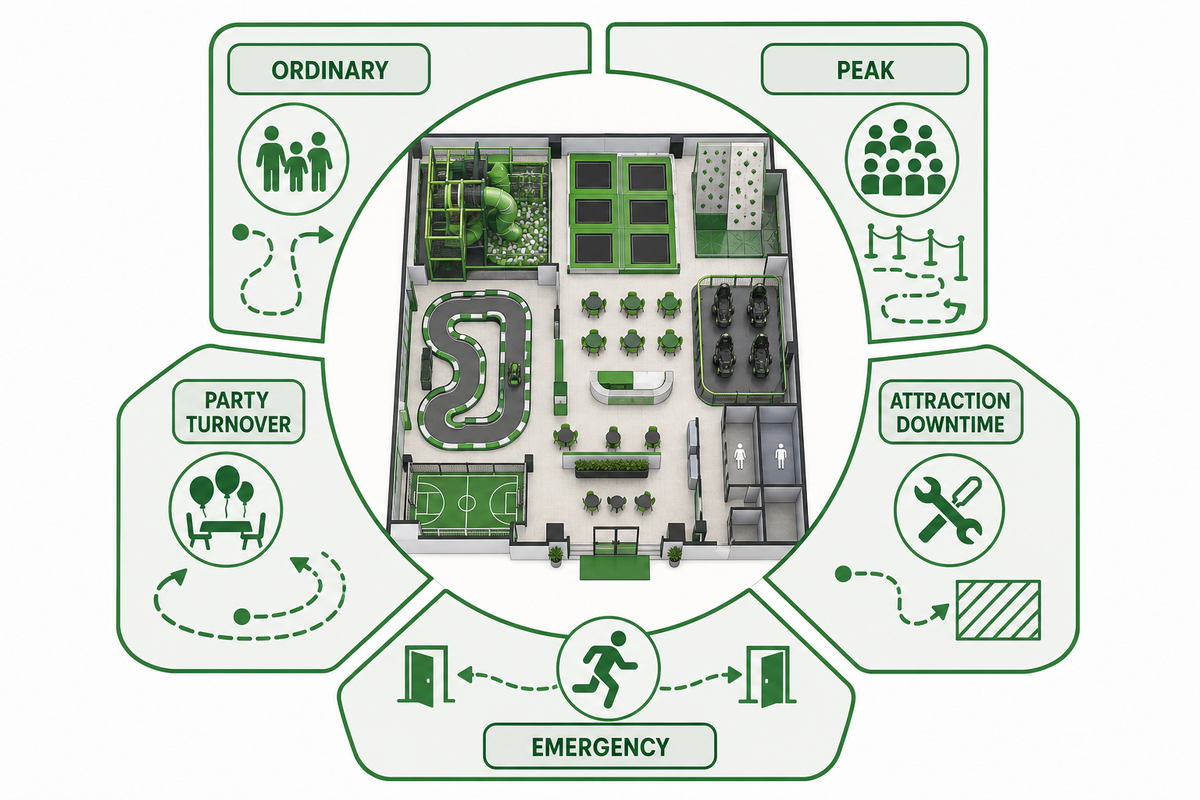
An attraction mix should assign each zone an operating role and test it under ordinary, peak, party-turnover, downtime, and emergency scenarios. With net area and clear height recorded, compare expected users, capacity assumptions, dwell, throughput, queue behavior, staffing, supervision, utilities, revenue role, and support-space demand; do not convert uncited commercial percentages into universal planning rules.
Demand is not one peak attendance number. A family entertainment center may receive small walk-in groups during one period, scheduled parties during another, and spectators who remain near seating areas while children move between multiple attractions. Each pattern changes foot traffic, queue overlap, staff positions, food and beverage demand, and the visitor experience.
Attraction Mix Fit Matrix
Attraction Mix Fit Matrix compares attraction roles against project variables; it is a planning worksheet, not a predictive scoring standard.
| Attraction type | Test first | Plan interface | Limitations / Not suitable for |
|---|---|---|---|
| Visual anchor | First-view impact and target audience fit | Entrance, wayfinding, clear height | Sites where the view blocks orientation or supervision |
| Capacity absorber | Operating capacity and staffing basis | Queue, entry control, seating | Plans without a verified capacity and queue envelope |
| High-throughput activity | Cycle, reset and loading pattern | Ticketing, circulation, staff station | Locations where discharge crosses another queue |
| Repeat-play activity | Replay motive and session length | Card system, prize or waiting area | Mixes that depend only on one-time novelty |
| Party driver | Group size, turnover and staging | Party rooms, food, storage, route | Routes that cross uncontrolled public queues |
| Toddler or quiet zone | Age fit and caregiver behavior | Seating, sightlines, controlled access | Adjacency to fast discharge or mixed-size play |
| Skill or prize zone | Play pattern and redemption journey | Arcade games, prize counter, storage | Plans with no waiting or prize-queue allowance |
| Food and beverage | Order, pickup, seating and waste routes | Kitchen, service access, acoustics | Positions that merge pickup and attraction queues |
| Spectator/support zone | Dwell and supervision needs | Seating areas, charging, visibility | Dead edges that obstruct circulation |
| Flexible/event zone | Changeover and storage method | Power, barriers, temporary signage | Use that compromises required routes when active |
Suppose a party group leaves its room while a popular attraction is restarting after downtime. The plan may work during ordinary attendance but fail when the party route, attraction queue, and food pickup line appear together. Draw that combined scenario before choosing a final zone share. The play-area zone mix planner can organize early inputs, but its output still needs scenario testing.
Common mistake: A percentage that appears on several vendor pages is still not a standard. Keep the number in the assumption register until its source, purpose, and project fit are known.
Solve Adjacencies Before Drawing the Guest Journey
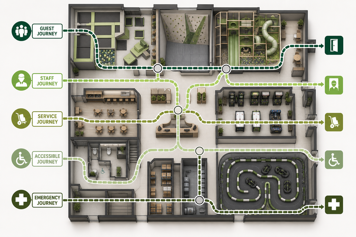
Adjacency planning decides which functions must be near, separated, visible, or service-connected before a circulation loop is polished. Use each party route, attraction queue, and food-pickup scenario to build the guest, staff, service, accessible, and emergency journeys independently, then overlay them; a short guest path is not an improvement if it transfers conflict into queuing, supervision, loading, or egress.
Start with an adjacency register rather than a pretty plan. For each pair of functions, label the relationship “must be near,” “prefer near,” “neutral,” “prefer separate,” or “must separate,” then record why. The reason matters because acoustics, food handling, visibility, staffing, and entrances and exits may point in different directions.
- Trace arrival — follow parking or mall approach, entrance, orientation, ticket counters and first decision point.
- Trace play — follow movement between multiple attractions, queues, seating areas and restrooms.
- Trace parties — follow check-in, staging, play, food service, belongings and departure.
- Trace service — follow staff, waste, stock, maintenance and emergency access without assuming guest routes are available.
- Trace access and egress — send the required paths to the qualified team for project-specific confirmation.
Imagine a parent at a seating area supervising two children in different zones. A central location may look efficient, yet a tall themed element, ticket counter, or queue rail can remove the useful sightline. The correction may be a changed adjacency, lower visual obstruction, different seating orientation, or a separate supervision rule—not simply “more open space.”
Wayfinding should reveal the next decision before guests reach a conflict. Clear signage can help, but signage does not repair a route that forces strollers, party groups, food pickup, and attraction discharge through one pinch point. Test the geometry first; use theming, interior design, and restrained brand cues to reinforce a legible route and guest experience afterward.
Run the FEC Flow Conflict Overlay
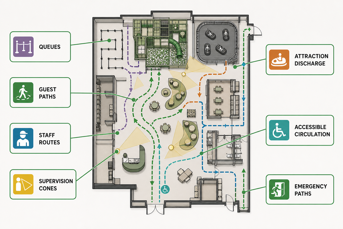
FEC Flow Conflict Overlay is a scenario review that marks where queues, guest paths, staff routes, supervision cones, attraction discharge, accessible circulation, and emergency paths compete. Red-line conflicts stay open until the team records each trigger, affected users, mitigation owner, verification method, and the drawing revision that resolves it.
FEC Flow Conflict Overlay
FEC Flow Conflict Overlay converts route collisions into owned, testable decisions instead of leaving them as informal drawing comments.
| Conflict test | Scenario trigger | Evidence or owner | Limitations / Not suitable for |
|---|---|---|---|
| Entrance and ticket queue | Group arrivals | Operating forecast and measured envelope | Do not borrow required circulation |
| Attraction queue spill | Peak or restart | Supplier data and operator scenario | No generic queue length |
| Accessible route overlap | Queue expansion | Accessibility professional | Operational preference cannot waive requirements |
| Exit-route overlap | Maximum permitted load | Code consultant and authority | Flow sketch cannot set exit capacity |
| Party turnover | One group exits as another enters | Booking and staffing plan | Average attendance hides the overlap |
| Food pickup and waste | Meal period | Food-service operator | Do not merge service and guest queues |
| Supervision blind spot | Queue or movable display added | Sightline review | A plan view alone may not reveal height obstruction |
| Mixed-size play | Age groups converge | Operating rule and equipment scope | No universal age-zone geometry |
| Slide discharge | Child lingers at exit | Supplier and CPSC design-review prompt | Prompt is not a substitute for equipment requirements |
| Ball-pool concealment | Slide or climb discharges nearby | Supplier and CPSC design-review prompt | Historical evidence is attraction-specific |
| Maintenance isolation | Attraction downtime | Maintenance and operations team | Do not assume the whole venue closes |
In 1996, the U.S. Consumer Product Safety Commission published a review based on six months of on-site work at 13 soft-contained-play centers. Investigators identified collision exposure around slide exits into ball pools, climbing equipment in ball pools, and mixed-age play. That evidence is dated and narrow, so this guide uses it to define design-review prompts—not current FEC-wide incident rates.
One practical test is to simulate a child lingering at a slide discharge while another child descends, then repeat the test with the discharge near a ball pool or climbing base. Add caregiver sightlines and staff response paths to the same overlay. The result should be a design question for the supplier and qualified team, not an invented clearance number.
Coordinate Safety, Accessibility, and Approval Before Freeze
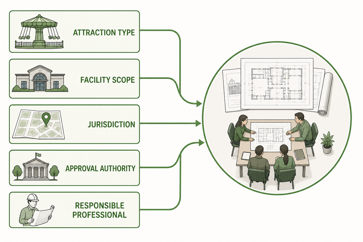
Safety and accessibility coordination starts by identifying attraction type, facility scope, jurisdiction, approval authority, and responsible professional. Those slide-discharge and ball-pool questions go to the supplier and team; operational traffic flow is one input only and does not determine permitted occupant load, exit-route capacity, accessible-route requirements, attraction-level access, equipment safety requirements, fire protection, or final permission to build and operate.
OSHA states that exit routes must support the maximum permitted occupant load and that their width must accommodate that load. The key planning lesson is not a universal aisle dimension. It is the separation of responsibilities: an FEC queue sketch can reveal an operational conflict, while the qualified code team and authority having jurisdiction determine occupant load, required exits, capacity, discharge, and local code application.
Accessibility also extends beyond tracing one route across the floor. The U.S. Access Board’s amusement-rides guide addresses load and unload areas, turning space, queue-entry signage, wheelchair spaces, ride seats designed for transfer, and transfer devices. Which provisions apply depends on the facility, attraction, alteration, and jurisdiction; the concept plan should reserve interfaces for review instead of claiming project approval.
| Question | Concept-plan action | Decision owner |
|---|---|---|
| Occupant load and exit capacity | Preserve routes and expose queue conflicts | Qualified code team and authority |
| Accessible route | Connect required spaces without queue encroachment | Accessibility professional and authority |
| Attraction-level access | Reserve load/unload and transfer interfaces | Supplier and qualified accessibility team |
| Soft contained play | Confirm the applicable F1918 scope | Supplier, inspector and authority |
| Amusement ride/device | Confirm attraction-specific standards | Qualified engineer, supplier and authority |
Standard titles are not interchangeable labels. ASTM F1918-21 is the active safety performance specification for soft contained play equipment. ASTM F2291-26, active as of July 15, 2026, covers amusement rides and devices but excludes soft play designed to F1918 from the practice in its entirety. IAAPA notes that ASTM F24 work spans design, manufacturing, testing, operation, maintenance, inspection, and quality assurance.
When not to freeze the layout: do not freeze equipment positions when the attraction classification, applicable standard, occupant-load basis, exit strategy, accessible interfaces, fire-protection coordination, or authority review path is still ownerless. A vendor concept image is not approval evidence.
Turn the Concept into a Decision-Ready Handoff
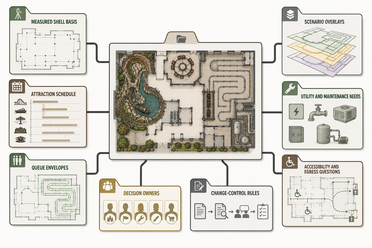
A decision-ready FEC handoff lets architects, engineers, attraction suppliers, operators, and approval authorities see the same assumptions and unresolved interfaces. Carry applicable F1918 or F2291 classification and playground equipment scope into a versioned plan with the measured shell basis, attraction schedule, queue envelopes, scenario overlays, utility and maintenance needs, accessibility and egress questions, decision owners, evidence links, and change-control rules.
Every handoff should state what the concept does not prove. It does not certify capacity, conformance, structural support, equipment performance, or approval. Instead, it organizes the questions and reserves the physical interfaces so the responsible party can answer them without reconstructing the family entertainment center design logic.
International teams may write family entertainment centre while U.S. project documents use “center.” Pick one spelling for controlled drawings and define the alternative once in the glossary; otherwise the same family entertainment centre can appear as two unrelated facility types in schedules and comments.
- Freeze the survey basis — identify drawing version, measurement source and open field checks.
- Issue the assumption register — assign owner, due date, evidence and change trigger to every provisional input.
- Attach the attraction schedule — include role, footprint source, queue envelope, staffing, utilities and maintenance access.
- Attach route overlays — show guest, party, service, accessible and emergency interfaces separately.
- Record red-line conflicts — keep unresolved items visible with mitigation and verification status.
- Confirm approval interfaces — name the qualified discipline and authority responsible for each decision.
- Control revisions — require each footprint or operating change to identify affected layers before acceptance.
Late supplier footprint changes are useful handoff tests. If the attraction schedule, queue envelope, utility point, maintenance route, and adjacent seating are linked to one revision, the team can assess the change. If the concept is only a rendered floor plan, the same change can quietly create several unrelated clashes.
Dreamland’s 2026 mall play-area design trends article owns time-sensitive trend intent; this guide keeps the planning method stable. When the brief is ready for commercial scoping, use Dreamland’s FEC project planning and equipment support page for configuration, supplier, installation, and quotation discussions.
FAQ: FEC Floor Plan Questions
These answers summarize the planning method without turning project variables into universal design rules. Actual dimensions, capacities, attraction standards, accessibility provisions, fire and life-safety requirements, and approval steps must be confirmed for the specific building, operating model, jurisdiction, and equipment selected.
What is the best layout for a family entertainment center?
Short answer
Choose the layout that satisfies the verified shell, target audience, attraction roles, operating scenarios, staffing, support spaces, accessible interfaces, and egress review with the fewest unresolved conflicts. Loop, branch, and hybrid routes can each work. Compare them against the same scenario register instead of declaring one pattern a universal winner.
How much space should each FEC attraction receive?
Short answer
Assign space only after confirming the supplier footprint, operating capacity basis, queue envelope, required access, loading and unloading, supervision, maintenance, utilities, and adjacent support functions. Add seating, storage, barriers, and staff positions before accepting the net zone. Reviewed sources did not establish universal FEC zone ratios, so any early percentage belongs in the assumption register until project data validates it.
How do you plan traffic flow in an indoor entertainment center?
Short answer
Trace arrival, orientation, play, food, parties, restrooms, prize redemption, and departure during ordinary trade, group arrival, party turnover, attraction downtime, and emergency conditions. Overlay queues, staff and service paths, sightlines, accessible circulation, and emergency interfaces on separate layers. For every collision, record the triggering scenario, affected users, responsible owner, planned mitigation, verification method, and drawing revision. Clear signage can support a legible route, but it cannot repair poor geometry or waive a required path.
Should food and beverage be near the entrance or the attractions?
Short answer
Test ordering, pickup, seating, supervision, deliveries, waste, acoustics, party service, and queue interaction. Entrance and attraction adjacencies each carry trade-offs; reject either option when service and guest routes collide.
When should an FEC operator hire an architect or code consultant?
Short answer
Bring qualified local professionals in before the concept freezes whenever occupant load, exits, accessibility, structure, fire protection, building services, change of use, permits, or attraction-specific rules can affect the plan. Early review can change the net usable area, route locations, clear-height assumptions, equipment placement, and approval schedule. Give the team the measured shell, attraction short list, operating scenarios, queue assumptions, and unresolved questions; do not ask them to certify a marketing render after procurement decisions are already fixed.
Turn assumptions into a project brief
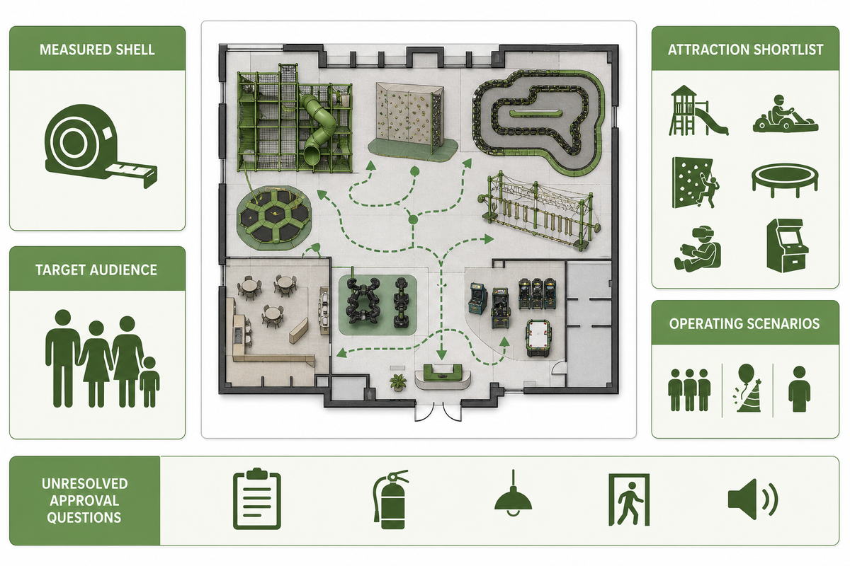
Bring the measured shell, target audience, attraction shortlist, operating scenarios, and unresolved approval questions. Dreamland can use that brief to discuss commercial configuration and equipment scope without confusing a concept plan with final professional approval.
Editorial boundary: This article provides a planning and coordination method, not architectural, engineering, code, accessibility, safety, or permitting approval. Project requirements must be confirmed by qualified professionals, suppliers, inspectors, and the authority having jurisdiction.
References & Sources
- Play Hard with Soft Contained Playgrounds — Playground Professionals
- CPSC Soft Contained Playground Safety Review — U.S. Consumer Product Safety Commission
- Soft Contained Play Equipment Safety Checklist — U.S. Consumer Product Safety Commission
- Design and Construction Requirements for Exit Routes — U.S. Occupational Safety and Health Administration
- Chapter 4: Accessible Routes — U.S. Access Board
- Chapter 10: Amusement Rides — U.S. Access Board
- 2010 ADA Standards for Accessible Design — U.S. Department of Justice
- ASTM F1918-21: Soft Contained Play Equipment — ASTM International
- ASTM F2291-26: Design of Amusement Rides and Devices — ASTM International
- ASTM Standards and the F24 Committee — International Association of Amusement Parks and Attractions